Commercial kitchen exhaust systems handle extreme heat, grease-laden vapors, and constant use that demands precise safety measures. The Type 1 hood duct clearance code in The Woodlands centers on safe exhaust termination and separation requirements that protect buildings and occupants from fire hazards.
These clearance specifications address minimum distances from doors, windows, adjacent buildings, ground level, air intake openings, combustible materials, and roof lines. We coordinate these separations during design to ensure grease exhaust systems terminate safely while maintaining access for inspection and cleaning throughout the building’s operational life.
What Wall Exhaust Termination Clearances Are Shown For Type I Hood Ducts?
Type I hood wall exhaust terminations require specific minimum distances from building openings and property boundaries. The clearance diagram shows that exhaust outlets must be positioned 10 feet horizontally from doors, windows, and adjacent buildings. Ground clearance requires the termination to be at least 10 feet above grade level.
Property line setbacks follow the same 10-foot horizontal rule for wall terminations. This distance prevents grease-laden vapors from affecting neighboring properties or creating code violations. We coordinate these measurements during the design phase to ensure adequate space exists for proper placement.
Combustible materials near the wall termination need careful consideration during layout. The exhaust outlet must maintain sufficient separation from combustible construction elements. We verify that the discharge direction moves grease-laden exhaust away from sensitive materials and building surfaces.
Field measurement becomes critical before cutting wall penetrations or installing core drilling equipment. We measure from the proposed termination point to all doors, windows, and operable openings within the required distance. The exhaust outlet location must prevent vapor impact on these openings during normal operation.
Exhaust outlet positioning affects both code compliance and building performance. We position terminations so the discharge direction minimizes impact on doors, windows, and neighboring structures. The grease-laden exhaust stream should not create maintenance issues or safety concerns for building occupants.
How Should Exhaust Terminations Be Separated From Air Intakes And Roof Elements?
Type I hood exhaust terminations require specific clearances from air intakes to prevent re-entrainment of grease-laden vapors. Code diagrams establish minimum horizontal distances of 10 feet between exhaust outlets and air intake openings. When this horizontal separation cannot be achieved, vertical separation provides an alternative with exhaust outlets positioned at least 3 feet above any air intake within 10 feet horizontally.
Intake height becomes critical when planning rooftop configurations. Air intakes positioned above the plane of the exhaust termination need additional clearance calculated at 10 feet plus 3 inches for each degree from horizontal. This angular measurement extends from the center of the exhaust termination to the center of the air intake opening.
Roof line clearance requirements protect building integrity and ensure proper exhaust dispersion. We maintain minimum distances between termination points and roof edges, parapets, and structural elements. The exhaust must discharge away from roof surfaces with adequate vertical clearance to prevent grease accumulation on building materials.
Combustible separation protects adjacent materials from heat exposure and grease deposits. Horizontal spacing of at least 5 feet separates exhaust outlets from combustible construction elements. This clearance applies to wood framing, siding materials, and other flammable building components near the termination point.
Re-entrainment prevention requires careful coordination of exhaust direction and nearby openings. We position terminations to direct exhaust flow away from windows, doors, and mechanical intakes. Cross-contamination risks increase when exhaust patterns intersect with fresh air pathways, making proper orientation essential for system performance.
Which System Components And Access Features Matter For Compliance And Maintenance?
We approach kitchen exhaust system design by identifying each critical component that requires ongoing inspection and maintenance access. The canopy serves as the capture point for cooking vapors, while the main fan provides primary exhaust power and the inline fan assists with system balance. Each component must be positioned to allow proper servicing throughout the system’s operational life.
Ductwork routing becomes a fundamental concern when we plan access panels for inspection openings. We coordinate with mechanical engineers to ensure grease ducts include cleanout points at direction changes and intervals that meet NFPA 96 requirements. These access panels allow thorough cleaning of interior surfaces where grease accumulates over time.
Fan placement requires careful coordination with ductwork layout to maintain code-required clearances at termination points. We document sections that become difficult to reach during construction and work with our installation teams to modify routing before systems become inaccessible. This proactive approach prevents compliance issues that arise when cleaning access becomes limited or impossible.
System documentation includes marking non-accessible ductwork sections on our construction drawings. We identify these areas during design review and coordinate alternative cleaning methods or system modifications. Our field teams verify that all critical components remain serviceable before final installation, ensuring long-term maintenance capabilities align with operational requirements.
Conclusion And Next Steps
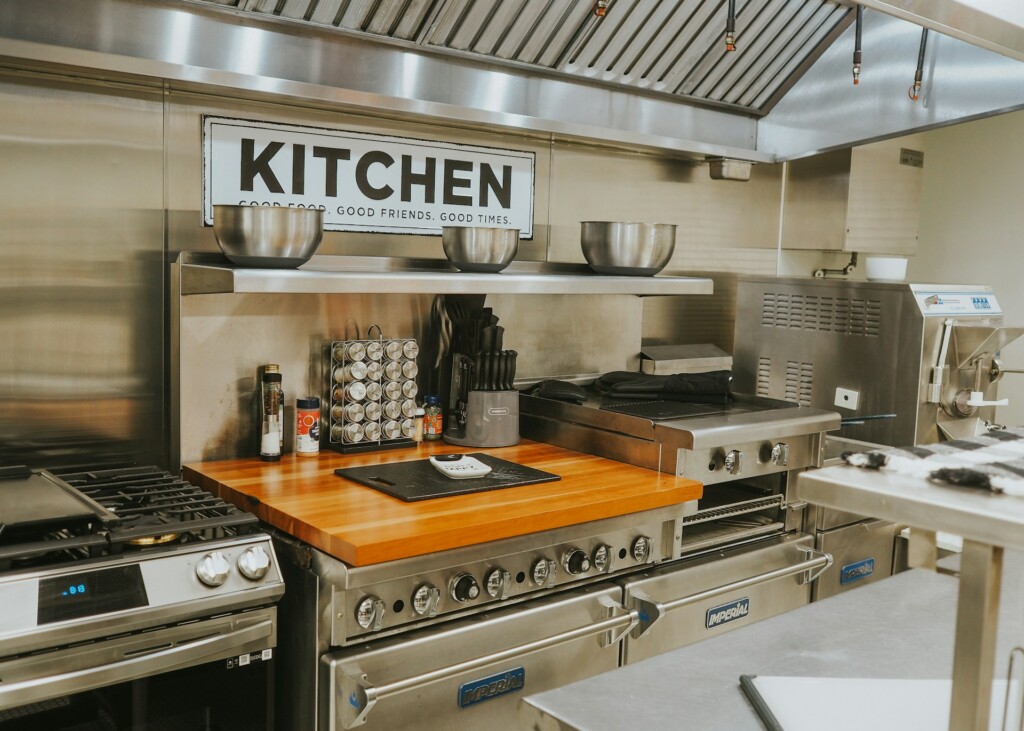
We coordinate Type 1 hood duct clearance code requirements with The Woodlands project specifications to ensure compliant exhaust termination placement. Our team verifies the 10-foot minimum distances from doors, windows, adjacent buildings, and property lines during the design phase. We measure clearances from ground level and air intake openings according to the mechanical code termination standards to prevent grease-laden vapors from impacting neighboring structures or recirculating through building systems.
We establish access panel locations throughout the duct system so maintenance teams can inspect and clean all grease duct sections effectively. Our construction process includes field verification of clearances before cutting or coring operations begin. We document final exhaust termination locations and duct routing on as-built drawings to support ongoing facility operations and code compliance inspections.
Ready to ensure your commercial kitchen exhaust system meets all clearance requirements? Contact EB3 for expert installation and compliance verification.
