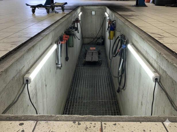
Auto bay trench drain detail in Round Rock specifies linear drainage systems that capture surface water flowing across service bays, vehicle ramps, and commercial driveways. These systems use channel drains equipped with grated covers and outlet connections to manage stormwater runoff effectively. We encounter these installations regularly in automotive facilities where proper water management prevents flooding and protects both vehicle operations and structural foundations.
The typical detail includes a precast polymer or stainless steel trench body paired with a load-bearing frame and protective grates designed for vehicular traffic. Round Rock drainage contractors offer comprehensive services including drainage system setup, channel drain installation, linear drain setup, grate installation, and ongoing drainage trench maintenance to ensure optimal performance throughout the system’s lifespan.
Which Components And Materials Are Shown In Typical Auto Bay Trench Drain Details?
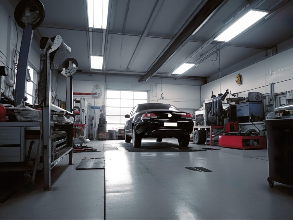
Technical drawings from auto bay trench drain specifications reveal several critical components that make these systems function effectively in vehicle service environments. The diagrams consistently show precast polymer trench bodies as the primary channel element, offering durability and chemical resistance for automotive applications. These polymer channels work alongside stainless steel trench sections that accommodate heavier loads and provide corrosion resistance.
Load-bearing frames appear prominently in the details as structural elements that distribute vehicle weight to the surrounding concrete. Cast iron grates fit within these frames, creating the visible surface that allows water entry while supporting traffic loads. The specifications include notes on HDCL grating as an alternative option for certain installations, particularly in ramp applications where specific load ratings or drainage patterns are required.
Installation hardware forms another key component group shown in the drawings. Installation brackets mount to the channel body and provide connection points for securing the system during concrete placement. Reinforcement elements integrate at slab interfaces, ensuring proper structural continuity between the drain assembly and the surrounding pavement. Anchor clips secure grated covers to their frames while allowing removal for maintenance access.
The modular design approach appears consistently across the technical details. Bolt-together sections allow field assembly of longer drain runs while maintaining watertight connections. These sections connect through mechanical joints that can accommodate thermal movement and settling without compromising the drainage path.
Outlet assemblies represent the final component category shown in the drawings. Vitrified clay gully traps connect to trench outlets and provide transition points to underground storm systems. PVC perforated buckets function as debris baskets within these outlet assemblies, capturing sediment and preventing downstream blockages. The deep channel profiles visible in ramp trench drain details accommodate higher flow volumes and steeper grades typical of vehicle access areas.
How Is Layout And Installation Organized For Round Rock Auto Bays And Ramps?
We organize auto bay trench drain installation through a structured sequence that addresses drainage patterns, channel placement, and system connections. The process starts with site assessment and progresses through elevation setting, component installation, and final connections to downstream infrastructure.
Site Assessment And Drainage Planning
Our first step involves assessing drainage patterns and identifying low spots across the service area. We examine where water naturally flows during rain events, noting areas where surface water collects near bay thresholds, ramp inverts, or driveway crossings. This assessment determines the optimal linear drain setup locations and helps us understand the site’s water runoff solutions needs.
For auto bay applications, we focus on areas where vehicles transition from higher to lower elevations, such as service bay entrances and ramp approaches. The evaluation process includes measuring existing slopes and identifying any grade changes that could affect channel drain installation effectiveness.
Channel Drain Positioning And Elevation
After completing the site assessment, we plan the linear drain setup along critical drainage points. Channel drains get positioned at bay thresholds where vehicles enter service areas, at ramp inverts where slopes change direction, and at driveway crossings where surface water management becomes essential.
Setting proper channel drain elevation relative to both the slab and driving surface requires careful coordination. We ensure the drain channels sit flush with finished concrete surfaces while maintaining adequate slope toward outlets. For ramp trench drain applications, details show deep channels positioned to collect flow heading directly to inlet points.
Load-Bearing Frame And Grate Installation
Once we establish proper elevations, we install load-bearing frames that support both the drainage system and vehicle traffic loads. These frames anchor into the concrete slab using installation brackets and reinforcement specified in the design details. The frames must align precisely with final grade elevations to prevent vehicle damage or drainage problems.
Grate installation service follows frame placement, with grated covers designed to handle auto bay traffic while maintaining drainage capacity. We secure grates using anchor clips and ensure they integrate properly with the channel body design.
Downstream Connections And System Integration
The final installation step connects trench drains to catch basins or downstream stormwater drains. These connections ensure collected surface water flows to appropriate disposal points rather than creating standing water problems. We coordinate catch basin installation with the overall drainage system setup to maintain proper flow patterns.
Round Rock service scopes include comprehensive stormwater drain installation that ties individual channel sections into the broader water management infrastructure. Our approach ensures each component works together to handle surface water effectively while meeting local drainage requirements.
What Grate And Frame Options Match Auto Bay Traffic And Use?
Drawings from auto bay installations highlight cast iron grates as the standard solution for vehicle areas. These grates seat directly into load-bearing frames designed to support the weight and frequency of automotive traffic. The cast iron construction provides durability against constant wheel loads while maintaining the structural integrity needed for safe vehicle passage.
Stainless steel trench bodies paired with cast iron grates represent the most common configuration in auto bay drainage examples. This combination balances corrosion resistance in the channel body with proven load capacity in the grate system. The stainless steel resists automotive fluids and cleaning chemicals while the cast iron grates handle vehicle impacts and loading cycles.
HDCL grating appears in ramp details where specific load requirements or drainage characteristics are needed. These heavy-duty options complement cast iron grates in applications where enhanced flow capacity or specialized mounting becomes necessary. The selection depends on ramp grades, traffic patterns, and drainage volume requirements.
Grated covers lock into load-bearing frames through mechanical connections that integrate with the overall channel body. This locking mechanism prevents grate displacement during vehicle passage while maintaining access for cleaning and maintenance. The frame and grate work as a unified system rather than separate components.
Anchor clips and installation brackets provide the structural connection between frames and the surrounding concrete or slab build-up. We position these hardware elements during the concrete pour to ensure proper frame elevation and prevent movement during curing. The brackets distribute loads from the frame into the surrounding concrete matrix, creating a stable platform for vehicle traffic.
What Outlet Connections And Maintenance Details Are Included?
Design drawings depict a vitrified clay gully trap as the primary outlet connection from the trench system. This trap connects directly to the channel outlet and provides a reliable path for water to flow from the drainage channel into downstream piping. The trap design includes sediment settlement capabilities that help prevent debris from moving further into the stormwater infrastructure.
A PVC perforated bucket appears in several detail examples as a debris basket within the outlet assembly. This bucket sits inside the gully trap and catches sediment, leaves, and other materials before they can obstruct downstream connections. The perforated design allows water to pass through while retaining solid debris for easy removal during maintenance cycles.
Channel sections utilize bolt-together construction with anchor clips for secure assembly and maintenance access. Grated covers lock into position over these sections, allowing maintenance crews to lift individual grates without disturbing adjacent areas. The anchor clip system ensures sections remain properly aligned while providing removal points when deeper cleaning becomes necessary.
Round Rock drainage trench maintenance protocols focus on keeping flow paths clear through regular inspections and cleaning. Maintenance tasks include grate removal for access, debris clearing from channels and outlet connections, and inspection of catch basins to verify proper drainage function. The bolt-together design facilitates these maintenance activities by allowing crews to access specific sections without major excavation work.
We coordinate routine outlet inspections to check gully trap function and sediment bucket capacity. Regular debris removal from PVC perforated buckets prevents overflow conditions that could compromise the entire water management infrastructure. These maintenance practices ensure consistent drainage performance across auto bay installations in Round Rock’s service environment.
Conclusion And Next Steps

Auto bay trench drain detail in Round Rock centers on linear channels that manage surface water across service bays and ramps. The key components include load-bearing frames that support vehicular traffic, grated covers that allow water entry while filtering debris, and secure connections to catch basins and storm lines. Channel bodies feature polymer or stainless steel construction for durability in automotive environments.
The referenced drawings illustrate specific material choices for Round Rock applications. Cast iron and HDCL grates provide the strength needed for vehicle loading. Anchoring hardware like clips and installation brackets ensure proper integration with concrete slabs. Outlet connections include vitrified clay gully traps and PVC perforated buckets that function as debris baskets to maintain flow capacity.
To move forward with your drainage project, map low spots and drainage patterns across your auto bay areas. Select channel widths and grate types that match your expected traffic loads and surface water volumes. Plan outlet connections to existing catch basins or design new gully trap locations for proper stormwater management. Contact EB3 Construction for your auto service shop build out and schedule professional drainage system installation for your Round Rock facility.
