Commercial kitchen build-outs fail inspections for predictable reasons; hood systems that don’t meet NFPA 96 clearance requirements, permit drawings that trigger repeated RFIs, MEP rough-ins that have to be relocated after walls close, and wall finishes that don’t satisfy health plan-check criteria. Every one of those failures traces back to a decision that could have been resolved during design.
Getting the compliance sequence right before construction begins is what keeps the project on schedule and out of correction cycles.
Commercial Kitchen Build-Out Compliance: Permits, NFPA 96, Suppression Systems, and Health Code Requirements
Start with the Local Health Department
The sequence of permit coordination matters as much as the permits themselves. Before a lease is signed, we engage with the local health department to confirm which sanitation standards, equipment configurations, and facility requirements will apply to the specific space. Different jurisdictions adopt varying versions of the FDA Food Code, so getting clarity from the authority having jurisdiction (AHJ) early shapes every downstream construction decision.
Staff certifications and the retail food business license follow directly from that initial health department review. Most jurisdictions require food handler certification for employees involved in food preparation or service, typically within 30 days of hire. The retail food business license is issued only after a health inspection confirms that the facility’s sanitation procedures, equipment selections, and physical layout meet code. That timing means the construction sequence must be planned so the space is ready for that inspection without rework.
Align Building, Zoning, and the Certificate of Occupancy Early
A Certificate of Occupancy (CO) is issued only after all inspections pass, covering MEP rough-in, fire suppression, egress, and structural elements. A commercial kitchen cannot legally open without it. We verify zoning compliance before rough-in begins because a conflict discovered after walls are framed forces costly redesigns that delay the entire project.
Coordinating with the building department, fire marshal, and health department at the same time prevents one approval from triggering a redesign for another. When zoning is confirmed and building review is sequenced alongside health plan review, the path to a CO stays clear and predictable rather than reactive.
Coordinate MEP Designs to UMC and NEC Before Permit Submission
Local jurisdictions adopt versions of the Uniform Mechanical Code (UMC) and the National Electrical Code (NEC) that govern how HVAC, plumbing, and electrical systems are designed and installed. NEC compliance covers grounding, circuit sizing, GFCI protection in wet zones, and panel labeling. The UMC governs ventilation, gas connections, and makeup air supply.
We align mechanical, plumbing, and electrical designs with the locally adopted codes before permit drawings are finalized. When MEP coordination happens after design decisions are locked in, contractors end up repositioning rough-ins that have already been inspected, which adds change orders and significantly extends permitting timelines.
Submit Permit-Ready AutoCAD Sets with Full Detail
Permit-ready AutoCAD drawings must show equipment locations, utility connection points, ventilation paths, fire suppression systems, and accessibility requirements in enough detail for health and fire reviewers to evaluate compliance without issuing excessive Requests for Information (RFIs). Drawings that show exactly where suppression nozzles land relative to cooking surfaces, how gas shutoffs are accessible, and which circuits carry GFCI protection move through plan review faster than sets that require repeated clarification.
The FDA’s Food Establishment Plan Review Guide underscores this: listing and locating equipment on floor plans and diagramming specifications for electrical, mechanical, and plumbing systems lets reviewers spot potential problems on paper before costly purchases, installations, and construction begin. When permit sets are thorough and accurate at submission, approval timelines compress and costly field changes become far less likely.
Use BIM Clash Detection Before MEP Rough-In
We use BIM to overlay all building systems in three dimensions before construction starts. Ductwork, gas piping, electrical conduit, and plumbing are modeled together so clashes are caught on screen rather than in the field. Hood placement determines the exhaust duct routing path to the roof, and that path cuts through structural bays, ceiling plenums, and mechanical spaces already claimed by other systems.
Clash detection resolves these conflicts at the design stage, when changes cost a fraction of what they do after rough-in is complete. That level of coordination reduces RFIs during construction and gives permit reviewers a drawing set that reflects how the systems will actually be built. Three-dimensional renderings of the final layout also give owners and kitchen operators a clear picture of equipment placement before construction locks anything in.
Field-Verify Existing Conditions and Document As-Builts at Closeout
Renovation projects carry a specific risk: conditions behind walls and under slabs rarely match the original drawings. We capture existing conditions through field verification before finalizing any design for a kitchen expansion or remodel. Accurate baseline data prevents surprises during demolition and keeps permit drawings grounded in actual site conditions rather than assumptions.
As-built documentation produced at construction closeout records the exact location of every rough-in, every shutoff valve, and every circuit as installed. Future modifications, equipment upgrades, or health department re-inspections all benefit from a complete record of what was built. Without that documentation, the next contractor working in the space starts from guesswork rather than verified facts, which creates unnecessary risk during future inspections or upgrades.
What NFPA 96 Hood And Grease Duct Requirements Must Installations Meet?
Type I Hood Placement And Coverage
NFPA 96 requires Type I hoods over all cooking equipment that produces grease-laden vapors. Wall-mounted canopy hoods must be positioned no more than 4 feet above the cooking surface, and gas equipment should sit at least 6 inches inside the hood perimeter on all open sides to ensure adequate capture.
Hood face velocity is a practical concern during plan check. Some AHJs enforce a minimum face velocity of about 50 feet per minute to confirm the hood draws grease-laden air inward rather than allowing it to spill into the kitchen. We size hood overhangs and exhaust rates to meet the physical placement requirements and the airflow performance expectations of the local AHJ before permit submittal.
Grease Duct Material And Welding Standards
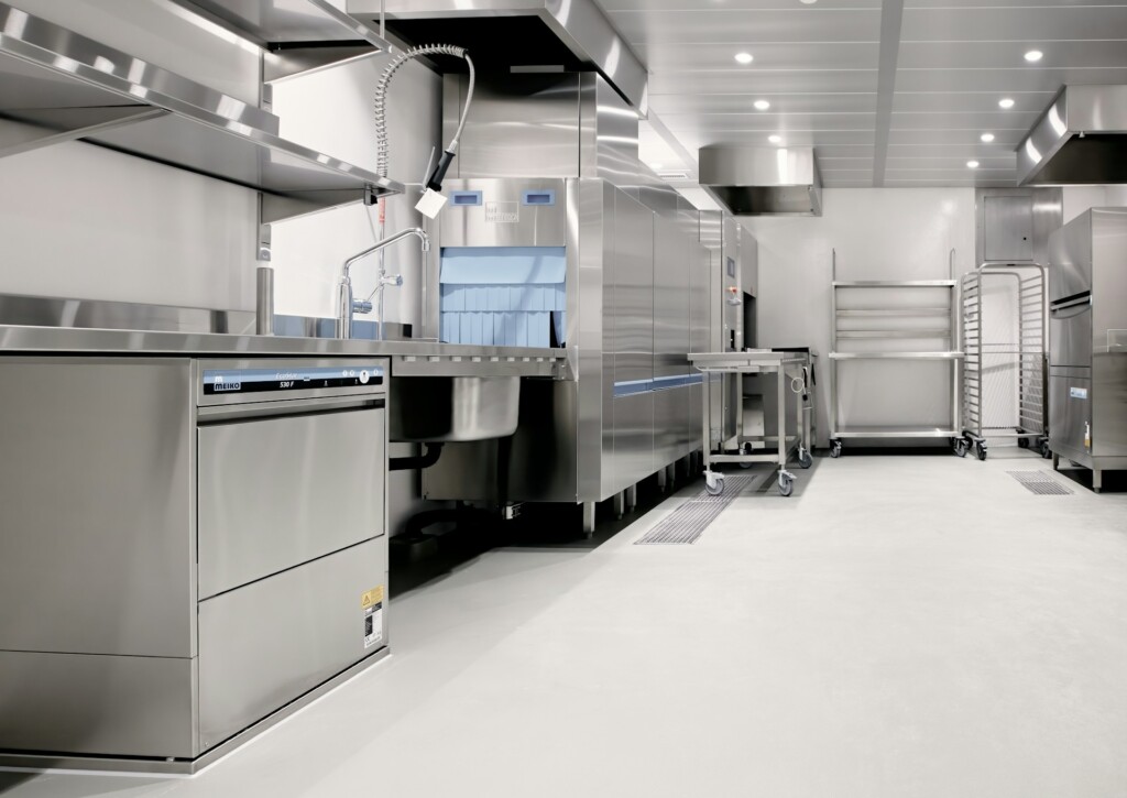
Field-fabricated grease ducts must be constructed from carbon steel at a minimum thickness of 0.055 inch (16-gauge) or from stainless steel at a minimum thickness of 0.044 inch (18-gauge). Aluminum and galvanized steel are prohibited in grease duct systems regardless of application or location in the run.
Every joint and seam in a grease duct assembly requires a continuous, liquid-tight external weld. Partial welds, mechanical fasteners, or sealant-only connections do not satisfy this requirement. We detail duct fabrication specifications on the permit drawings and coordinate with the mechanical subcontractor to verify welding quality before concealment during rough-in.
The interior surface of the duct must remain smooth to support cleaning and grease transport. Duct runs should follow direct vertical or horizontal paths with minimal bends, reducing the number of direction changes, keeping cleaning intervals manageable, and limiting access panel requirements in constrained ceiling conditions.
Access Panel Spacing And Construction
Access panels are required at intervals not exceeding 12 feet along the duct run and at every change of direction. This spacing ensures that cleaning contractors can reach the entire interior of the duct system without leaving unverified sections where grease can accumulate. Panels must be sized to allow thorough access, with 20-inch by 20-inch openings where duct dimensions permit.
Each access panel must be constructed from the same material and gauge as the duct itself and must form a grease-tight closure. A common field failure occurs when other trades block access panel clearances after rough-in, rendering cleaning and inspection impractical. We coordinate panel locations in the BIM model and flag clearance zones during construction sequencing to prevent this from becoming a closeout deficiency.
Clearances To Combustibles And Listed Wrap Systems
Grease ducts must maintain a minimum 18-inch clearance from all combustible construction. This separation limits the risk that heat radiating from the duct during or after a grease fire will reach surrounding framing, insulation, or finish materials. The requirement applies along the full length of the duct, including where it passes through walls, ceilings, and floor assemblies.
The 18-inch clearance can be reduced only by using a listed fire-rated enclosure or a listed wrap system installed in accordance with the manufacturer’s instructions and the product’s listing. The allowable reduction depends on the specific listed assembly and requires AHJ approval before installation. We confirm listed wrap compatibility with the local fire marshal during early design coordination, not during rough-in inspection, so the enclosure detail is resolved on the permit drawings before work begins.
How Are Ventilation Controls, Monitors, And Fire Suppression Integrated For Compliance?

Gas Monitors, Fan Controls, and the Interlock Logic Fire Marshals Verify
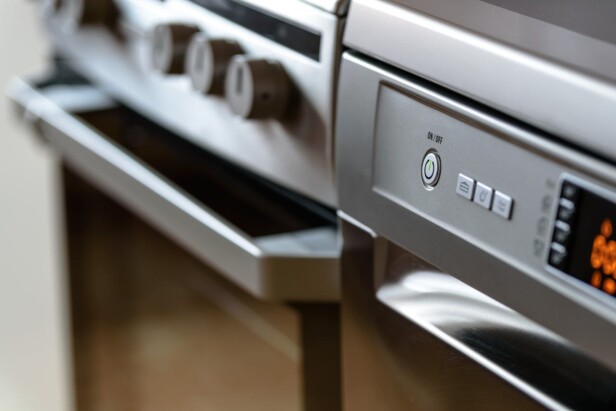
Many jurisdictions require CO, CO2, or oxygen monitors tied directly to the exhaust system or fuel shutoff, depending on local code adoption. When sensors detect hazardous gas concentrations, interlocks cut the fuel supply and, depending on the equipment listing or local amendment, may also shut off supply fans or exhaust fans. Fire marshals routinely check this interlock logic during both plan check and field review.
Timer-controlled exhaust fans are frequently prohibited under the International Mechanical Code and local amendments. Fans must operate on demand-based or cook-activated controls so ventilation stays active whenever cooking is in progress. A simple timer creates a gap in which the hood runs on a fixed schedule, independent of actual cooking, which violates code in most jurisdictions.
Makeup Air Sizing and Negative Pressure Prevention
Makeup air must be sized to replace approximately 90 percent of the exhausted air volume. Undersizing this supply creates negative pressure inside the building, which pulls unconditioned air through gaps, compromises hood capture performance, and creates backdraft conditions that affect both air quality and fire safety.
The makeup air unit must be interlocked with the exhaust fan so both systems operate together. When the exhaust fan runs, so does the makeup air unit. This coordination prevents the pressure imbalance that develops when exhaust volume consistently outpaces supply. We resolve makeup air unit sizing and interlock sequencing during MEP coordination, before rough-in begins, so the relationship between the two systems is built into the permit drawings from the start.
UL 300 Wet Chemical Suppression Coverage and Shutoff Interlocks
UL 300 wet chemical suppression systems must cover the cooking surface of every appliance under the hood, the hood interior plenum, and the duct collar. Fusible links trigger automatic discharge, and the system must interlock with both gas and electrical shutoffs so all appliances under the hood lose power and fuel the moment the system activates. A gap in either shutoff connection is a plan check rejection and a certificate of occupancy hold.
Nozzle coverage requirements are appliance-specific. Salamander broilers, griddles, char broilers, ranges, woks, and deep-fat fryers each requires dedicated nozzle positions directly above the appliance. We coordinate suppression contractor drawings with the permit set we submit for fire marshal review, so nozzle placement, appliance locations, and gas shutoff valve accessibility are documented together rather than submitted as separate packages that reviewers must reconcile.
Manual pull stations must be positioned near exits so kitchen staff can trigger the system during an emergency, even if automatic detection fails. NFPA 17A Section 5.2 requires both automatic and manual actuation capability for any listed wet chemical system. We confirm pull station locations during layout coordination so the final equipment arrangement does not block access or conflict with egress paths.
Class K Extinguishers, Egress, and Life Safety Requirements
At least one Class K portable extinguisher is required within 30 feet of commercial cooking equipment under NFPA 96. Class K agents are specifically formulated for high-temperature cooking fats and oils. A standard dry chemical unit does not satisfy this requirement, and inspectors flag the distinction during the final walkthrough. We confirm extinguisher placement during rough-in coordination so the kitchen layout does not create an obstruction between the extinguisher and the cooking zone it covers.
Egress paths must remain clear, properly signed, and illuminated at all times. The applicable life safety code governs exit signage specifications, emergency lighting requirements, and minimum clear widths for egress corridors and door openings. Non-slip flooring in cooking and service zones satisfies both OSHA requirements and health department expectations, given the combination of wet surfaces and heavy foot traffic. We address egress and life safety requirements during the MEP and layout coordination phase so these elements are built into the construction sequence rather than addressed as corrections after framing is complete.
Which Wall Finishes And Details Meet Health Plan-Check Expectations, And Where Are They Required?
Under California Retail Food Code Section 114271, approved wall finishes must be smooth, durable, nonabsorbent, and easily cleanable. Those four criteria are not interchangeable; a surface can be smooth yet still absorb moisture, which means it fails the standard regardless of how well it resists abrasion. We treat all four criteria as a single package when specifying materials during the plan check phase.
The requirement applies to specific areas: food preparation, packaging, and storage zones; utensil and equipment storage; warewashing areas; restrooms and handwashing stations; service areas and wait stations where sinks or food and beverage equipment are located; indoor garbage and refuse storage; janitorial facilities; walk-in refrigerators and freezers; and self-service food and beverage areas. Dining rooms, sales floors, offices, and consumer-only restrooms have different or reduced requirements under the code, so scope boundaries matter during plan development.
Height and Width Requirements for Wall Finish Coverage
Height requirements vary by area type. Food preparation zones and warewashing or other wet areas require a minimum of 8 feet of compliant finish measured from the finished floor. Restrooms and areas surrounding janitorial facilities require a minimum of 4 feet. These are floor-measured heights, not heights measured from the top of a cove base, which is a distinction some local guides clarify explicitly.
Width coverage adds a lateral dimension that drawings need to capture clearly. Approved finishes must extend at least 3 feet beyond any open food preparation equipment, sinks, or plumbing fixtures. Walls adjacent to warewashing machines often require coverage at least 18 inches on each side of the equipment, and some county guides specify 8 feet of coverage behind dishwashing machines because of the high moisture output in those zones. We document these extents on the finish schedule submitted with permit drawings so the health plan checker can verify compliance without requesting additional details.
Acceptable and Unacceptable Materials, and Trim Details
Gloss or semi-gloss enamel paint, epoxy paint, fiberglass-reinforced polyester panels (FRP), stainless steel, and ceramic tile are among the materials most commonly accepted under Section 114271. Each comes with conditions. Paint applied over a textured substrate fails because the base surface is not smooth. FRP is generally prohibited adjacent to cooking equipment in several county guides, where heat-resistant materials such as stainless steel or ceramic tile are required instead. Ceramic tile requires grout that is sealed and impervious to water, grease, and acid, and some jurisdictions require a tile sample for review before installation.
Materials that are consistently rejected include exposed brick, concrete block, rough concrete, rough plaster, grooved paneling, wood paneling, wallpaper, and vinyl wall coverings. Textured gypsum board falls into this category as well. The logic behind these rejections is straightforward: surface irregularities trap grease, moisture, and biological material that routine cleaning cannot remove.
Trim is a frequently overlooked detail during plan check. All corners, edges, and joints in required areas must be sealed with appropriate trim to eliminate gaps where contamination can accumulate. We specify corner bead, edge trim, and joint molding on the finish schedule and coordinate with the installer to ensure no open seams remain at transitions between wall panels or between the wall finish and adjacent equipment. A missing trim detail at a sink backsplash or panel joint is a common correction item at preliminary inspection, and addressing it in the drawings avoids that friction.
Local Variation and the District Inspector Review Process
Section 114271 sets the statewide baseline, but county and city environmental health departments often publish their own approved finish guides that provide additional detail. Alameda County, Riverside County, San Bernardino County, and Los Angeles County each maintain documents that list accepted and rejected materials, note where samples are required, and in some cases specify product characteristics such as wear-layer thickness or panel installation methods. A finish that clears a Berkeley plan check may still require additional documentation in a San Diego submittal.
Because of this variation, we confirm material selections with the local district inspector before purchase or installation when the product is not explicitly listed in the applicable county guide. Manufacturer specification sheets and physical samples may be required as part of that review. Completing this step before materials are procured prevents costly substitutions after rough-in. The finish schedule included in our permit drawings identifies the material type, color, surface finish, and brand name for each room or area, giving plan checkers the details they need to approve or flag materials without back-and-forth on generic descriptions.
Conclusion And Next Steps

Every system covered in this article—permits, AHJ coordination, MEP rough-in, NFPA 96-compliant hoods and ducts, suppression interlocks, and code-compliant wall finishes—depends on decisions made before construction starts. The projects that reach final inspection without costly field corrections are the ones where compliance planning runs parallel to design, not behind it. A site assessment that maps existing utilities to the equipment layout, permit drawings that satisfy both the health department and fire marshal, and BIM-coordinated MEP sets that catch clashes before rough-in—these are the actions that compress timelines and reduce rework.
Sequencing those actions correctly often determines whether commercial kitchen build-outs stay on schedule or fall behind. Confirming which versions of local health and fire codes apply, aligning wall finish specifications with plan-check expectations, and coordinating suppression coverage with hood placement are not tasks that can be addressed at closeout. Each task shapes the next, and when one is delayed, the entire permit and inspection sequence shifts. At EB3 Construction, we manage that sequence from initial permit coordination through final inspection, keeping every trade and every code requirement aligned throughout the build-out.
Contact EB3 Construction to start planning your inspection-ready commercial kitchen build-out today.