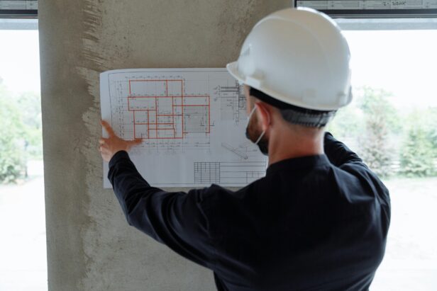
Commercial construction blueprints are the foundation of every major building project. These technical drawings serve as a universal language, allowing architects, engineers, contractors, and other stakeholders to communicate complex design intentions clearly and consistently. At EB3 Constriction, we believe the ability to accurately interpret these plans is an indispensable skill.
At their core, blueprints provide detailed specifications that guide the entire construction process. They incorporate standardized symbols, notations, and scales to efficiently convey a wealth of information about dimensions, materials, installation methods, and building techniques. This standardization enables blueprints to compress an enormous amount of data into a format that can be quickly understood by trained professionals.
Mastering blueprint reading opens up several key advantages in commercial construction:
- Allows for precise execution of the architect’s vision, ensuring the final structure matches the intended design
- Helps identify potential issues or conflicts early in the process before they become costly problems
- Facilitates clear communication between different trades and specialties working on the project
- Provides a common reference point for estimating costs, ordering materials and scheduling work
While the prospect of deciphering complex technical drawings may seem daunting at first, the fundamentals of blueprint reading can be learned relatively quickly. With practice, construction professionals can develop the ability to rapidly extract critical information from plans and visualize how various elements will come together in the finished building.
In this guide, we’ll walk through the essential components of commercial construction blueprints and provide practical tips for interpreting them effectively. Whether you’re new to the field or looking to enhance your existing skills, understanding how to read these vital documents will prove invaluable throughout your career in commercial construction.
What Are the Key Components of Commercial Construction Blueprints?

At EB3 Construction, we work with detailed construction drawings that contain several critical components. These elements work together to provide a comprehensive view of the commercial projects we undertake. The key components typically include:
Floor Plans
Floor plans offer a bird’s-eye view of each level of the building. We analyze these drawings closely as they show the layout of rooms, placement of walls, and locations of key features like doors and windows. For our commercial clients, floor plans are essential for visualizing how spaces will function and flow.
Elevations
Elevation drawings provide vertical views of the building’s exterior and interior walls. As we coordinate construction, these drawings guide our understanding of the building’s aesthetic and functional elements from each side. Elevations are particularly important for ensuring the proper placement of windows, doors, and exterior finishes.
Section Drawings
Section drawings offer a cut-through view of the building, revealing the relationships between floors, ceilings, and structural components. We rely on these drawings to understand complex vertical relationships within the building, such as stairwells, elevator shafts, and mechanical systems.
Drawing Scales
Each component of the blueprint set is drawn to a specific scale, which is always noted on the page. Understanding and working with these scales is crucial for accurate interpretation and execution of the design intent. We ensure our team is well-versed in reading and applying these scales across all project phases.
The interplay between these components is what allows us to construct a complete picture of the project. As we coordinate with architects, engineers, and subcontractors, we reference these drawings constantly to ensure every aspect of the building is constructed according to plan.
For commercial projects, additional specialized drawings often come into play. These may include:
- Mechanical, electrical, and plumbing (MEP) plans
- Structural drawings
- Site plans showing the building’s location on the property
- Detail drawings that zoom in on specific building elements
By thoroughly understanding how these components work together, we at EB3 Construction can effectively translate the architect’s vision into reality, ensuring that every commercial project we undertake is built to exact specifications.
| Blueprint Component | Description |
| Floor Plans | A bird’s-eye view of each level of the building, showing the layout of rooms, walls, doors, and windows. |
| Elevations | Vertical views of the building’s exterior and interior walls, ensuring proper placement of windows, doors, and finishes. |
| Section Drawings | A cut-through view of the building, showing the relationships between various structural components. |
| Drawing Scales | Indicates the scale used in the blueprint, crucial for accurate interpretation and execution. |
| MEP Plans | Mechanical, electrical, and plumbing plans are specialized drawings that include HVAC, electrical layouts, and plumbing routes. |
Our experience in interpreting these complex sets of drawings allows us to anticipate potential issues before they arise on the job site. This proactive approach helps minimize delays and keeps commercial construction projects on schedule and within budget.
As construction methods and technologies evolve, so too do the ways in which blueprints are created and shared. While traditional paper drawings are still used, we’re increasingly working with digital blueprints and 3D building information models (BIM). These advanced tools enhance our ability to visualize the project holistically and coordinate more effectively across all trades involved in the construction process.
How Do You Interpret Common Blueprint Symbols and Notations?
At EB3 Construction, we understand that interpreting blueprint symbols and notations is vital for efficient project execution. Construction drawings use a standardized visual language to convey complex information effectively. Let’s look at some of the most common symbols you’ll encounter and how we interpret them:
Architectural Symbols
The foundation of any blueprint is the architectural symbols representing core building elements:
- Doors: We recognize doors as straight lines with arcs indicating the swing direction, which helps in planning for clearances and traffic flow.
- Windows: Typically depicted as parallel lines with breaks, window symbols guide us in understanding fenestration patterns and natural light considerations.
- Walls: Single or double lines of varying thicknesses indicate different wall types. We pay close attention to line weight to distinguish load-bearing walls from partitions.
Material Hatch Patterns
Different materials are represented by specific fill patterns, known as hatching:
- Concrete: Often shown with a dot or stipple pattern
- Brick: Represented by staggered rectangles mimicking actual brickwork
- Wood: Typically indicated by parallel lines simulating wood grain
These patterns allow us to quickly identify material transitions across large areas of the blueprint without extensive labeling.
Electrical Symbols
Electrical plans use a distinct set of symbols to map out power and lighting systems:
- Outlets: Typically shown as circles or ovals
- Switches: Often depicted as small squares with lines indicating the type of switch
- Light fixtures: Represented by various symbols depending on the fixture type
Our electrical subcontractors use these symbols to ensure proper placement and wiring of all electrical components.
Plumbing and HVAC Symbols
Mechanical systems have their own symbolic language:
- Pipes: Shown as lines with different patterns for various types of piping
- Fixtures: Toilets, sinks, and other plumbing fixtures have simplified iconic representations
- Ductwork: Indicated by parallel lines, often with arrows showing airflow direction
These symbols help our mechanical teams coordinate complex systems within the building envelope.
Structural Symbols
Structural drawings use symbols to represent load-bearing elements:
- Columns: Often shown as rectangles or circles, sometimes with crosshatching
- Beams: Represented by thick lines, usually accompanied by dimensional information
- Footings: Depicted with specific shapes indicating the type and size of foundation
Our structural engineers and concrete teams rely on these symbols to ensure the building’s integrity and load distribution.
Using Drawing Legends
While many symbols are standardized, variations can occur between different architectural firms or project types. That’s why we always carefully review the drawing legend included with each set of blueprints. This legend acts as a key, defining any unique or project-specific symbols used throughout the drawings.
By mastering the interpretation of these symbols and notations, we at EB3 Construction ensure clear communication across all trades involved in a project. This shared understanding is crucial for translating two-dimensional plans into fully realized, three-dimensional structures that meet our clients’ expectations.
Interpreting blueprint symbols accurately is just one aspect of successful project execution. Our team’s expertise extends beyond symbol recognition to comprehensive project management, ensuring that every detail on paper becomes a reality on the construction site.
How Do You Use Legends and Schedules in Commercial Blueprints?

Legends and schedules are essential tools for interpreting commercial construction blueprints. We use these references to efficiently communicate detailed information about building elements and systems without cluttering the main drawings. Here’s how we leverage these components in our blueprint reading process:
Blueprint Legends
Legends serve as comprehensive dictionaries for blueprint symbols. We typically position them as the first sheet in a drawing set to provide a central reference point. When reviewing plans, we consult the legend to understand:
- What each symbol represents (e.g., electrical outlets, plumbing fixtures, structural elements)
- The meaning of abbreviations and acronyms used throughout the drawings
- Line types and weights that indicate different building systems or components
By familiarizing ourselves with the legend upfront, we can quickly interpret symbols as we move through the rest of the drawing set, improving our efficiency and accuracy.
Construction Schedules
Schedules provide detailed information about specific building elements. We use these tabulated lists to find specifications for items such as:
- Doors – sizes, materials, fire ratings, hardware sets
- Windows – dimensions, glazing types, frame materials
- Fixtures – model numbers, finishes, mounting heights
- Finishes – materials, colors, locations
Rather than crowding this information onto the drawings, schedules allow us to efficiently look up the exact specifications we need. We cross-reference schedule numbers with symbols on the plans to get a complete picture of each element.
Keynotes and Drawing Annotations
Keynotes are a system of numbered or coded annotations that link explanatory notes to specific points in the drawings. We use keynotes to:
- Provide additional context or instructions for particular building elements
- Reference applicable specification sections for more detailed information
- Call out unique conditions or requirements without cluttering the visual representation
When reviewing plans, we make sure to read all keynotes carefully, as they often contain critical information not conveyed by the drawings alone.
Practical Application
In our day-to-day work, we integrate these tools into our blueprint reading process:
- Start by studying the legend to understand the ‘language’ of the drawings
- As we review plans, constantly refer back to schedules for detailed specifications
- Pay close attention to keynotes, which often highlight important considerations
- Use these references to build a comprehensive understanding of the project requirements
By effectively utilizing legends, schedules, and keynotes, we ensure we have a complete grasp of the project specifications. This thorough understanding helps us accurately estimate costs, plan construction sequences, and execute the work according to the design intent.
What Are MEP and Specialty Drawings in Commercial Blueprints?
Commercial blueprint packages include specialized drawings that are critical for bringing a building’s systems to life. Chief among these are Mechanical, Electrical, and Plumbing (MEP) drawings. These detailed plans ensure all building systems integrate seamlessly and function as intended.
Let’s Break Down the Key Components:
Mechanical Drawings
Mechanical drawings provide a comprehensive roadmap for HVAC systems. We meticulously place symbols representing ducts, vents, and air handlers to show how conditioned air will flow throughout the structure. These plans are indispensable for HVAC contractors, allowing them to visualize system layouts and identify potential conflicts before installation begins.
Electrical Drawings
When creating electrical drawings, we map out the building’s nervous system. We indicate precise locations for outlets, switches, and lighting fixtures. Our drawings also delineate circuits and panel locations, giving electricians a clear guide for wiring the structure safely and efficiently. This level of detail is crucial for ensuring adequate power distribution and code compliance.
Plumbing Drawings
Our plumbing drawings chart the course for water supply and waste management. We detail pipe routes, fixture placements, and essential components like water heaters and pumps. Plumbers rely on these plans to install systems that deliver water where it’s needed and remove waste effectively, all while adhering to local codes and regulations.
Reflected Ceiling Plans (RCP)
While not strictly an MEP drawing, Reflected Ceiling Plans (RCPs) play a vital role in coordinating ceiling-mounted elements. We create these plans as if viewing the ceiling from a mirror placed on the floor, hence the name ‘reflected.’ RCPs are invaluable for coordinating lighting fixtures, HVAC diffusers, sprinkler heads, and other overhead components.
The importance of these specialized drawings cannot be overstated. They serve as the primary communication tool between designers, contractors, and subcontractors. By providing clear, detailed plans for each system, we minimize on-site conflicts and ensure the smooth integration of all building components.
For example, a mechanical contractor can use our HVAC drawings to plan ductwork installation while simultaneously checking for conflicts with lighting fixtures shown on the RCP. This level of coordination is essential for efficient construction and long-term building performance.
Understanding and effectively using these specialized MEP and specialty drawings is a cornerstone of successful commercial construction. We ensure our drawings provide the detail and clarity needed for seamless coordination between trades, ultimately resulting in buildings that not only meet but exceed client expectations.
Conclusion: Mastering Commercial Blueprint Reading

Reading commercial construction blueprints is a foundational skill that involves understanding standardized symbols, scales, and drawing conventions. Familiarizing yourself with the different components of blueprint packages—from floor plans and elevations to specialized MEP drawings—will better equip you to interpret design intent and execute construction accurately. At EB3 Construction, we’ve observed firsthand how strong blueprint reading skills lead to smoother project coordination and fewer errors on site.
Blueprints serve as the universal language of construction, facilitating clear communication among architects, engineers, contractors, and other stakeholders. When our team masters this language, we’re able to translate complex design concepts into tangible structures more efficiently. We’ve found that developing proficiency in blueprint interpretation directly correlates with improved project outcomes and client satisfaction.
For construction professionals aiming to advance their careers, honing blueprint reading skills is an invaluable investment. The ability to quickly and accurately extract information from drawings sets you apart in the field. It enables more proactive problem-solving and allows for better anticipation of potential coordination issues before they arise during construction.
As the commercial construction landscape continues to evolve with increasingly complex designs and integrated building systems, the importance of expert blueprint reading only grows. We encourage all our team members and industry partners to continually refine these skills through practice, training, and exposure to diverse project types.
By prioritizing blueprint proficiency, we empower ourselves to deliver projects with greater precision, efficiency, and quality. This commitment to excellence in blueprint interpretation is one of the cornerstones of successful commercial construction management.
To learn more about how EB3 Construction leverages expert blueprint reading for superior project outcomes, contact our team today.
